Where are they used?
Open Frame Series
Keep Solenoid Series
Flapper Solenoid Series
Solenoid Valve Series
Tubular Solenoids
Product Inquiry
2-5-5, Shinmei-cho, OKAYA, Nagano,
394-0004, Japan
TEL: +81-266-23-4517
FAX: +81-266-23-4523
Access
Top Page > Technical Info > General Characteristics of DC Solenoid
Technical Info

General Characteristics of DC Solenoid

The following general characteristics are critical to select a solenoid using the Pull Force Characteristics of DC Solenoids (stroke/ pull force and power/ pull force graphs) in the data sheets.

1. Decrease in Pull Force due to Temperature Rise

Explanation Example
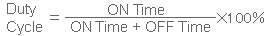
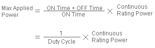
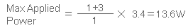
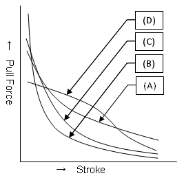
Given pull force characteristics in the data sheets are the measured values at an ambient temperature of 20℃. As a solenoid heats up, its pull force decreases. The coil resistance increases and flowing current decreases as the temperature rise of the solenoid and its ambient temperature rise when energized, resulting in the magnetomotive force to be smaller. The relationship between temperature and coil resistance can be calculated by the temperature coefficient of magnet wire wrapped around coil. Assuming 20℃ as 1, the relationship among temperature, resistance, and current can be described as the chart below.
Temp. (℃)02060100120
Resistance Ratio0.911.21.31.4
Current Ratio1.110.80.750.7
Pull Force decrease is the squared value of current: at 100℃, 0.75*0.75=0.56, thus, it decreases to approx. 60% of the force at 20℃.

2. Stroke

Explanation Example
Some of the solenoid selection criteria are stroke and pull force required by the application. To select a best suited solenoid, please also consider the duty cycle and the wattage applied. For a solenoid that operates at 4 mm Stroke with 2.94N (300g) Pull Force (a margin of safety is 1.8, thus, 5.3N (540g)), you can select either TDS-08A (13.6W) or TDS-10A (10W) by the Pull Force Characteristics.

3. Duty Cycle

Explanation Example
(A) Operation frequency is represented by duty cycle as shown below.
Energized (ON) time: 1 sec.
De-energized (OFF)time: 3 sec.
(B) A small duty cycle decreases the power consumption per second and increases margins for temperature rise, which allows applying a larger power. This means that a larger pull force can be obtained compared to that of a continuous operation rating. The maximum allowable power applied is limited by the continuous operation rating power specified by the temperature rise value (solenoid’s insulation class), which can be calculated by the formula below.
The continuous rating (duty cycle: 100%) for TDS-08A is 3.4W. Under the operating condition described above, the max applied power will be as following.

The max power of 13.6W can be applied. Under the 3.4W rating, the initial Pull Force at 4mm Stroke is 1.18N (120g) , while the Pull Force when 13.6W is applied becomes 5.3N (530g) according to the Pull Force characteristics curve. After temperature rise, a decreased Pull Force can be obtained by multiplying the current ratio in the above chart.
(C) The maximum ON time duration varies by model. We can select a best suited model to operating conditions required. Please feel free to contact us. With the applied power of 25% duty cycle, the time for Coil temperature to rise from 20℃ to 80℃ is as following.
  TDS-05C, 6.8W: Approx. 1 minute
  TDS-10A, 16.8W: Approx. 2 minutes

4. Plunger Angles

Explanation Example
(A)Most of the standard solenoids online come with plungers with 40 to 50°tapered configuration.
This type of Plunger is best suited for the Solenoid that the ratio of Stroke length (L) to Plunger diameter (D), L/D is about 0.2.
(B)Flat-faced plungers generally have 3 to 5 times larger holding force than (A).
This type of Plunger is suited when high Pull Force is required, or the ratio (L/D) is small (less than 0.1).
(C)Plunger with 90°angle generally have 1.5 to 2 times larger holding force than (A). This type of Plunger is suited for a solenoid required to operate at a stroke between (A) and (B).
Typical pull force/ stroke curves for various plunger face configurations.
(D)Stepped plungers may be suited when both pull force and holding force are important.

5. Residual Magnetism

Explanation Example
Solenoids with plunger face configuration as (B), (C) can obtain a relatively large holding force, but those of *Residual Magnetism also become larger. Residual magnetism tends to increase as plunger operations are repeated. Please consult with us separately if you require a small residual magnetism. Please consult with us separately if you require a small residual magnetism.

6. Life Expectancy

Explanation Example
Long life can be assured by a choice of surface finishing on the sliding surface of component (e.g. Plunger). Nickel coating
Molybdenum disulfide coating
Fluorocarbon resin coating

7. Noise Reduction/ Silencing

Explanation Example
Solenoids generate impact noise when plunger is attracted to the fixed core. This noise can be reduced by adding a cushioning material to the solenoid structure; however, it also lowers its holding force and pull force. There are silent solenoids with no fixed core installed inside that does not generate impact noise when plunger is pulled. Cushioning material: Rubber Damper
Structure: External noise reduction, Internal noise reduction.

8. Others

Please consult with us for other special/ customized design requirements for functions (e.g. push type, double-coil type, mold-coil type) or structures (e.g. terminal type, lead-wire type, connectors, thermal fuses, diodes).


Back To TOP
Inquiry